PETROLEUM GEOLOGY
  • Home
  • Introduction
  • Content
    • Petroleum Geochemistry
    • Origin of Petroleum >
      • Evaluation of Source Rocks
      • Generation & Migration
      • Geologic Time
    • Accumulation and Traps >
      • Basin Environment
      • Structural Trap
      • Stratigraphic Trap
    • The Reservoir >
      • The Subsurface Environment
      • Reservoir rocks >
        • Sedimentary rocks
        • Rock properties
      • Recovery Techniques
      • Conventional Fluids
      • Nonconventional Fluids
      • Petrophysics
      • Reservoir Estimation
    • Shale oil >
      • History of Shale oil
      • Oil Shale
      • Shale oil extraction
    • More about Petroleum >
      • Types of drilling bits
      • Drilling Fluids/Mud and Components
      • Oil-Rich Countries
      • Facts about Petroleum
      • Oil Measurement Unit
      • Forecast of Energy Usage
      • Exploration Techniques
      • Geologist & Engineer
      • Impacts on environment
      • World Reserves
      • Petroleum in Thailand
      • NOC & IOC
      • Digital Oilfields
      • Career in PE
      • Blowout Preventer(BOP)
      • HSE Basic Concepts
    • Geophysics >
      • Geophysical surveys for petroleum
    • From Exploration to Refining
    • Well logging
    • Real-Time Oil Price
    • Glossary of Oil and Gas Terms
  • Contact
  • About
  • Blog

Recovery Techniques 
(Extraction of petroleum)

1.) Primary recovery​​
​​     The majority of energy comes from reservoir, the natural mechanisms. These include expansion of the natural gas at the top of the reservoir, expansion of gas initially dissolved in the crude oil, natural water displacing oil downward into the well, and gravity drainage resulting from the movement of oil within the reservoir from the upper to the lower parts where the wells are located.
Picture
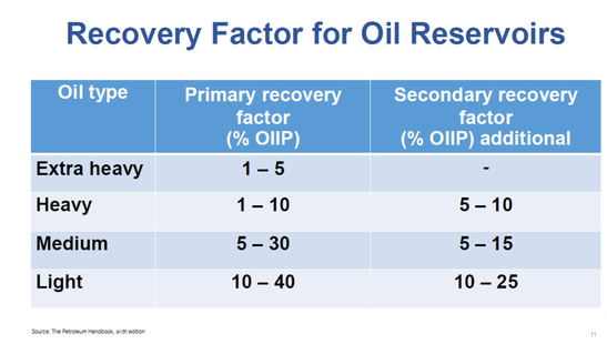
Recovery factor for oil reservoirs
Picture
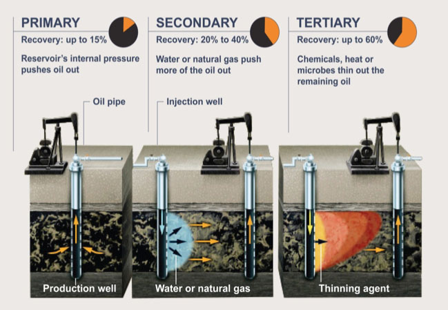
Recovery factor for each processes
2.) Secondary recovery
​     After the pressure falls and at some point, underground pressure is insufficient to force the oil to the surface. After natural reservoir energy decrease, secondary recovery methods are applied. They rely on the supply of external energy into the reservoir. Hence, secondary recovery techniques increase the reservoir’s pressure by water injection, natural gas reinjection and gas lift, which injects air, carbon dioxide or some other gas into the bottom of the well, reducing the overall density of fluid in the wellbore. on average, the recovery factor after primary and secondary oil recovery operations is between 35 and 45%, depending on the properties of the oil and the characteristics of the reservoir rock.
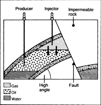
​Displacement of oil by water
​

Theoretical example to show the effect on displacement efficiency of viscosity and density differences between oil and water
Picture
Picture
Gas injection
3.) Enhanced oil recovery (EOR) or Tertiary recovery
     Increasing the mobility of the oil in order to increase extraction. According to the US department of Energy, there are three techniques for EOR which is thermal processes, gas injection(miscible processes) and chemical processes.
3.1) Thermal processes : using heat to reduce oil viscosity (for heavy oil)
   3.1.1 Surface heat generation
  • Hot water flooding : hot water is injected into the reservoir through specially distributed injection wells to reduce the viscosity of the crude oil, allowing it to move more easily toward production wells. Hot water flooding, also known as hot water injection, is typically less effective than a steam-injection process because water has lower heat content than steam. Nevertheless, it is preferable under certain conditions such as formation sensitive to fresh water.
  • Steam flooding : steam generated at surface is injected into the reservoir through specially distributed injection wells to heat up the crude oil and reduce its viscosity as same as hot water flooding but stream is more effective than hot water flooding because steam contains massive latent heat which is far more than specific heat of water.
  • Cyclic steam injection : steam is injected  and then subsequently put back on production. A cyclic steam-injection process includes three stages. The first stage is injection, during which a slug of steam is introduced into the reservoir. The second stage, or soak phase, requires that the well be shut in for several days to allow uniform heat distribution to thin the oil. Finally, during the third stage, the thinned oil is produced through the same well. The cycle is repeated as long as oil production is profitable. Cyclic steam injection is also called steam soak or the huff `n puff (slang) method.
Picture
Hot water flooding
Picture
Steam flooding
Picture
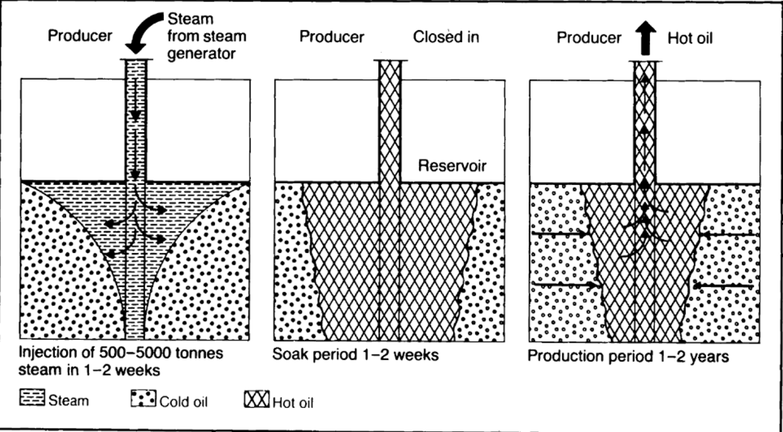
Cyclic steam injection (steam soak, or more colloquially, "huff and puff")
    3.1.2 Underground heat generation​
  • In situ combustion or fire flooding : a flame is generated in the reservoir by igniting a fire at the sand face of an injection well. Continuous injection of air or other gas mixture with high oxygen content will maintain the flame front. As the fire burns, it moves through the reservoir toward production wells. Heat from the fire reduces oil viscosity and helps vaporize reservoir water to steam. The steam, hot water, combustion gas and a bank of distilled solvent all act to drive oil in front of the fire toward production wells.
Picture
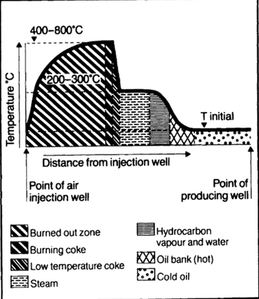
Temperature profile and fluid distribution in a reservoir during laboratory test of in situ combustion recovery process
3.2) Miscible processes : to create miscible zone to eliminate/reduce capillary force (for medium and light oil)
  • Hydrocarbon solvent injection : e.g. LPG, kerosene, gasoline.
  • Enriched hydrocarbon gas injection : A slug of methane enriched with propane, butane, or pentane and tailed by gas and/or water is injected into the reservoir.
  • High-pressure hydrocarbon gas injection : Miscible at high pressure. Continuous injection of high pressure methane, ethane, or flue gas into reservoir.
  • Carbon dioxide injection : Miscible at high pressure, dissolved in oil and reduction in viscosity.
  • Nitrogen injection : Miscible at high pressure, usually cheaper than carbon dioxide or a hydrocarbon derived gas.
Picture
Mobilisation of immobile oil
Picture
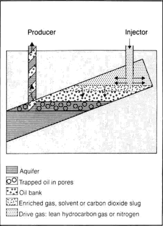
Solvent & Enriched gas & Carbon dioxide injection
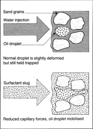
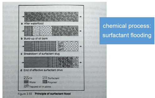
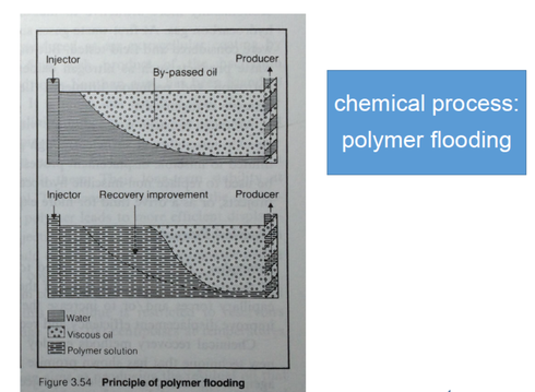
3.3) Chemical processes : to increase viscosity of displacing fluid (polymer flooding) and reduce capillary force (surfactant and caustic flooding)
  • Polymer flooding : Polymer dissolved in injected water in order to increase the water viscosity, to prevent bypassing and improve recovery.
  • Surfactant flooding : Soaps or soap-like chemical, attracted to water and oil forming micro-emulsion in order to reduce capillary force and also alter the wettability or the reservoir rock to improve oil recovery.
  • Caustic flooding : Also known as alkaline flooding in which an alkaline chemical such as sodium hydroxide or sodium carbonate is injected during polymer flooding or water flooding operations in order to reduce capillary force and interfacial tension between oil and water. Alkaline flooding is not recommended for carbonate reservoirs because of the abundance of calcium: the mixture between the alkaline chemical and the calcium ions can produce hydroxide precipitation that may damage the formation.
Picture
Surfactant flooding
Picture
Polymer flooding
Reference​
  • https://en.wikipedia.org/wiki/Extraction_of_petroleum#Enhanced_recovery
  • https://en.wikipedia.org/wiki/Enhanced_oil_recovery#Thermal_injection
  • http://www.glossary.oilfield.slb.com/Terms/h/hot_waterflooding.aspx
  • http://www.glossary.oilfield.slb.com/Terms/s/steamflood.aspx
  • http://www.glossary.oilfield.slb.com/Terms/c/cyclic_steam_injection.aspx
  • http://www.glossary.oilfield.slb.com/Terms/f/fire_flooding.aspx
  • http://csegrecorder.com/articles/view/enhanced-oil-recovery-techniques-and-nitrogen-injection
  • http://www.glossary.oilfield.slb.com/Terms/s/surfactant_flooding.aspx
  • http://www.glossary.oilfield.slb.com/Terms/a/alkaline_flooding.aspx
  • http://halliburtonblog.com/considerations-for-waterflooding-in-mature-fields-reservoir-optimization/
  • http://susris.com/wp-content/uploads//2014/01/figure1.jpg
  • The Petroleum Handbook, sixth edition
Picture

Go For the Food

To edit, click on the text to start adding your own words.
Picture
Picture
Powered by Create your own unique website with customizable templates.
Photo used under Creative Commons from NetReacher Imagery
  • Home
  • Introduction
  • Content
    • Petroleum Geochemistry
    • Origin of Petroleum >
      • Evaluation of Source Rocks
      • Generation & Migration
      • Geologic Time
    • Accumulation and Traps >
      • Basin Environment
      • Structural Trap
      • Stratigraphic Trap
    • The Reservoir >
      • The Subsurface Environment
      • Reservoir rocks >
        • Sedimentary rocks
        • Rock properties
      • Recovery Techniques
      • Conventional Fluids
      • Nonconventional Fluids
      • Petrophysics
      • Reservoir Estimation
    • Shale oil >
      • History of Shale oil
      • Oil Shale
      • Shale oil extraction
    • More about Petroleum >
      • Types of drilling bits
      • Drilling Fluids/Mud and Components
      • Oil-Rich Countries
      • Facts about Petroleum
      • Oil Measurement Unit
      • Forecast of Energy Usage
      • Exploration Techniques
      • Geologist & Engineer
      • Impacts on environment
      • World Reserves
      • Petroleum in Thailand
      • NOC & IOC
      • Digital Oilfields
      • Career in PE
      • Blowout Preventer(BOP)
      • HSE Basic Concepts
    • Geophysics >
      • Geophysical surveys for petroleum
    • From Exploration to Refining
    • Well logging
    • Real-Time Oil Price
    • Glossary of Oil and Gas Terms
  • Contact
  • About
  • Blog